
Basic Plc Wiring Diagram
PLC Control Panel Wiring refers to the process of connecting various electrical components, such as switches, relays, and sensors, to a programmable logic controller (PLC) in order to control and monitor different machinery or processes.

Plc Wiring Diagram Guide
1. Relay. A relay symbol in a PLC wiring diagram represents an electromagnetic switch that can control the flow of electricity to different parts of the system. Relays are commonly used to connect and disconnect power to various devices such as motors, lights, and sensors. 2.

Allen Bradley Plc Wiring Diagram Wiring Diagram Networks
Plc Panel Wiring Diagram Symbols: Understanding the Language of Automation As automation continues to revolutionize commercial and industrial operations, the ability to read and understand Plc Panel Wiring Diagrams is an ever more critical skill. These diagrams are used to represent the wiring of a control system and make it easier for technicians to diagnose, troubleshoot, and work with new.

Wiring Diagram With Plc Wiring Digital and Schematic
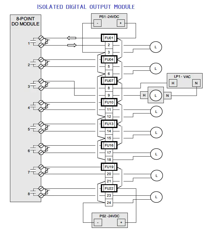
The following considerations will facilitate an orderly installation of a PLC: PLC I/O module installation Wiring considerations Recommended wiring procedures Wire size Wire and terminal labeling Wire bundling Special I/O connection precautions Connecting leaky inputs Suppression of inductive loads Fusing outputs Shielding I/O module installation
Single Line Wiring Diagram Plc Manual EBooks Plc Wiring Diagram
Please Subscribe to Easy PLC Training Sessions for more Videos and TrainingLink for Part # 1 PLC Tutorial for beginners Part #1 Hardware preview https://www..

Basic electrical design of a PLC panel (Wiring diagrams) EEP
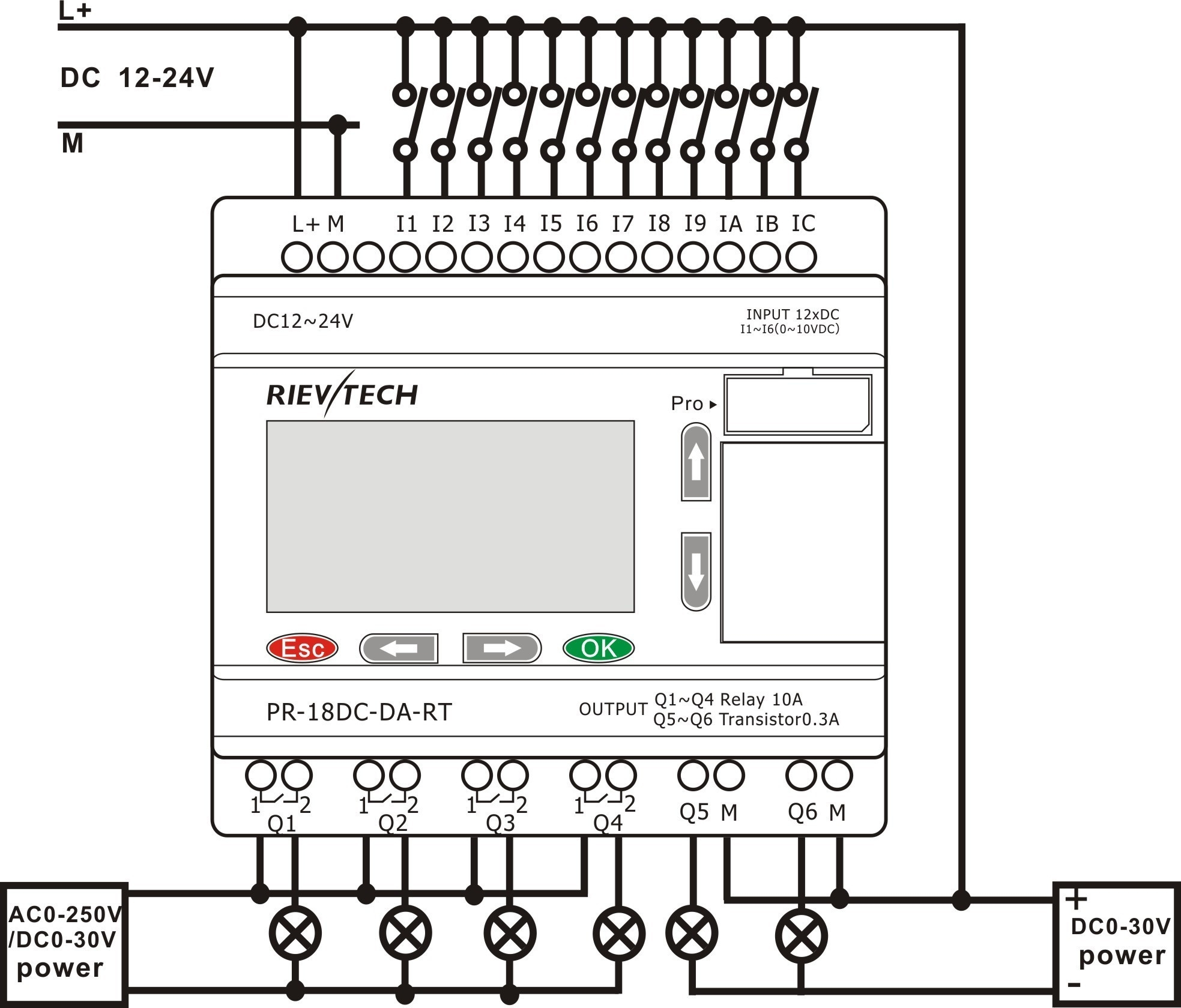
Now we have to understand that -v (0V) We need to create a potential difference of +V (24V) across these input terminals. Then only this PLC will recognize that there is some input. For example, if i connect this V over here (IN ). And then i am going to simulate that. You will see this is ON.
PLC Wiring Diagrams PLC Digital Signals Wiring Techniques
The operator panel is communicating to the PLC directly via the MPI port of the CPU using a Profibus cable. The WCDP5 cable is also a Profibus cable as it's connected to the DP port of the CPU. And you can read the color of the cable just beside of the cable tags. It is red with green stripes.
The Basics of Reading PLC Panels and Wiring Diagrams Do Supply Tech
Each page of this wiring diagram shows the exact wiring for different sections of this control panel. In the back of the Emergency Stop push button, you see that we have four wires, just as.
PLC Wiring Diagrams PLC Digital Signals Wiring Techniques
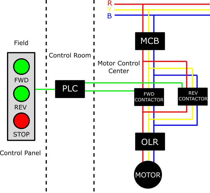
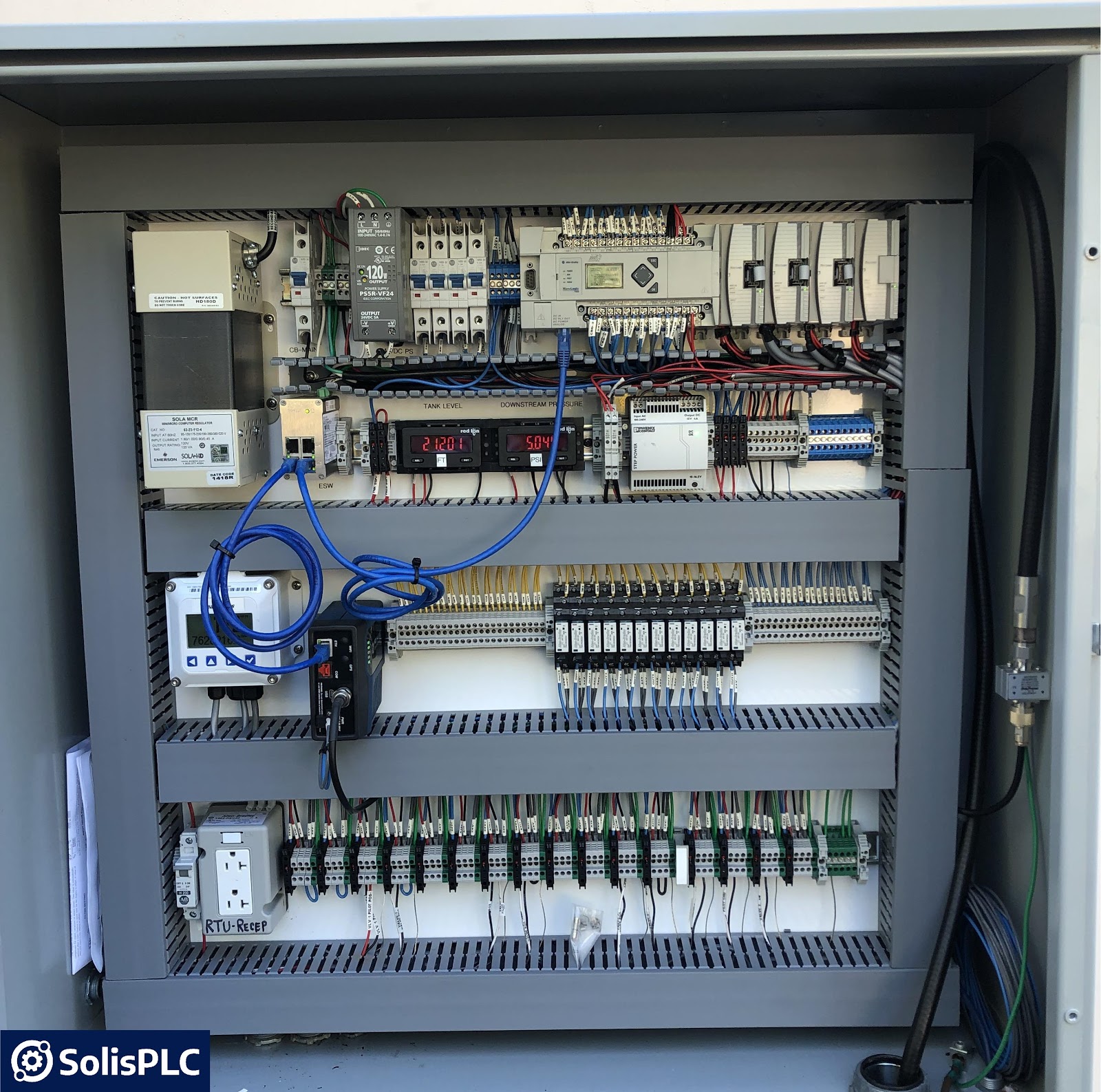
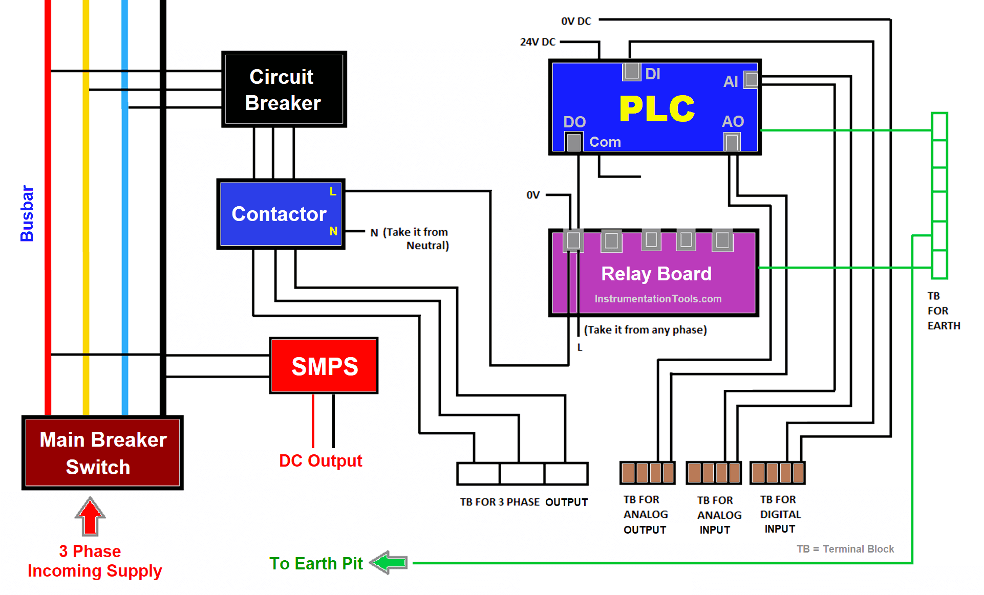
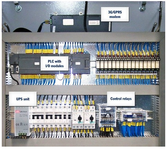
The PLC panel consists of the main breaker switch, bus bar, circuit breakers, relays, contactors, PLC, fuses, SMPS, terminal boards, utility sockets, and earthing points. Main Breaker Switch Let us start with the main breaker switch. This is the point where the main power supply (3 phases) is connected (R, Y, B, N).
Wiring Diagram Of Plc Panel Wiring Diagram Line
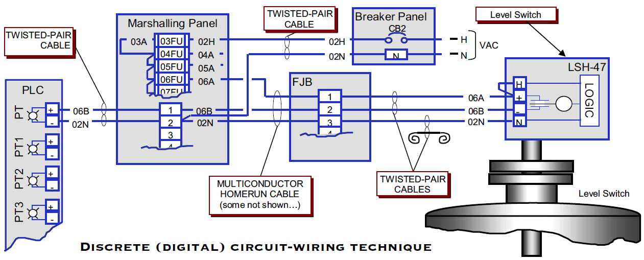
Wiring Diagrams of PLC and DCS The below list shows the basic types of wiring connections available for DI, DO, AI, and AO Signals: Digital Input (DI) Signals Single-wire Connection Two-wire connection Two-wire connection with Line Monitoring DI with Relay - Wet Contact DI with Relay - Dry Contact

PLC Panel Electrical panel wiring, Electrical projects, Electricity
With the right resources and knowledge, anyone can create an effective PLC wiring diagram that will ensure the best performance of a system. Basic Electrical Design Of A Plc Panel Wiring Diagrams Eep. The Basics Of Reading Plc Panels And Wiring Diagrams Do Supply Tech Support. Plc Wiring Diagrams Digital Signals Techniques
How To PLC Wiring In Control Panel The Automization
To be able to read an electrical wiring diagram of a PLC panel, you should have an understanding of these components. Let's take a look at these two types of electrical components: A) PLC Panel Power Components Rotary Disconnect: It is used for connecting incoming power lines/wires. It can include fuses or not.
Ban genius sunset plc layout
Electrical panel wiring diagrams are used to outline each device, as well as the connection between the devices found within an electrical panel. As electrical panels are what will contain control systems, panel wiring diagrams are commonly encountered by PLC technicians and engineers.
Panel eléctrico con PLC, Diseño básico (diagrama de cableado)
Electrical wiring diagrams of a PLC panel In an industrial setting a PLC is not simply "plugged into a wall socket". The electrical design for each machine must include at least the following components. Transformers - to step down AC supply voltages to lower levels

Wiring Diagram Of Plc Panel Derek Sanders
Basic Electrical Design of a PLC Panel (Wiring Diagrams) - Free download as PDF File (.pdf) or read online for free. When design PLC, we need a Panel to place our PLC safe and easy to manage. Following a guide to design PLC Panel is good to practice the good Panel arrangement.

Plc Control Panel Wiring Diagram on plc panel wiring diagram
In this comprehensive video guide, we dive deep into the art of wiring a Programmable Logic Controller (PLC) control panel. Whether you're a seasoned enginee.